The
Warping Machine self-control energy-saving device introduced in this example adopts the combination of light control and magnetic control, which can realize the automatic start and stop control of the warping machine.
Circuit Operation Principle The warping machine self-control energy saver circuit consists of a light control circuit, a magnetic control circuit, a +5V power supply circuit and a motor main control circuit, as shown in Figure 8-134.
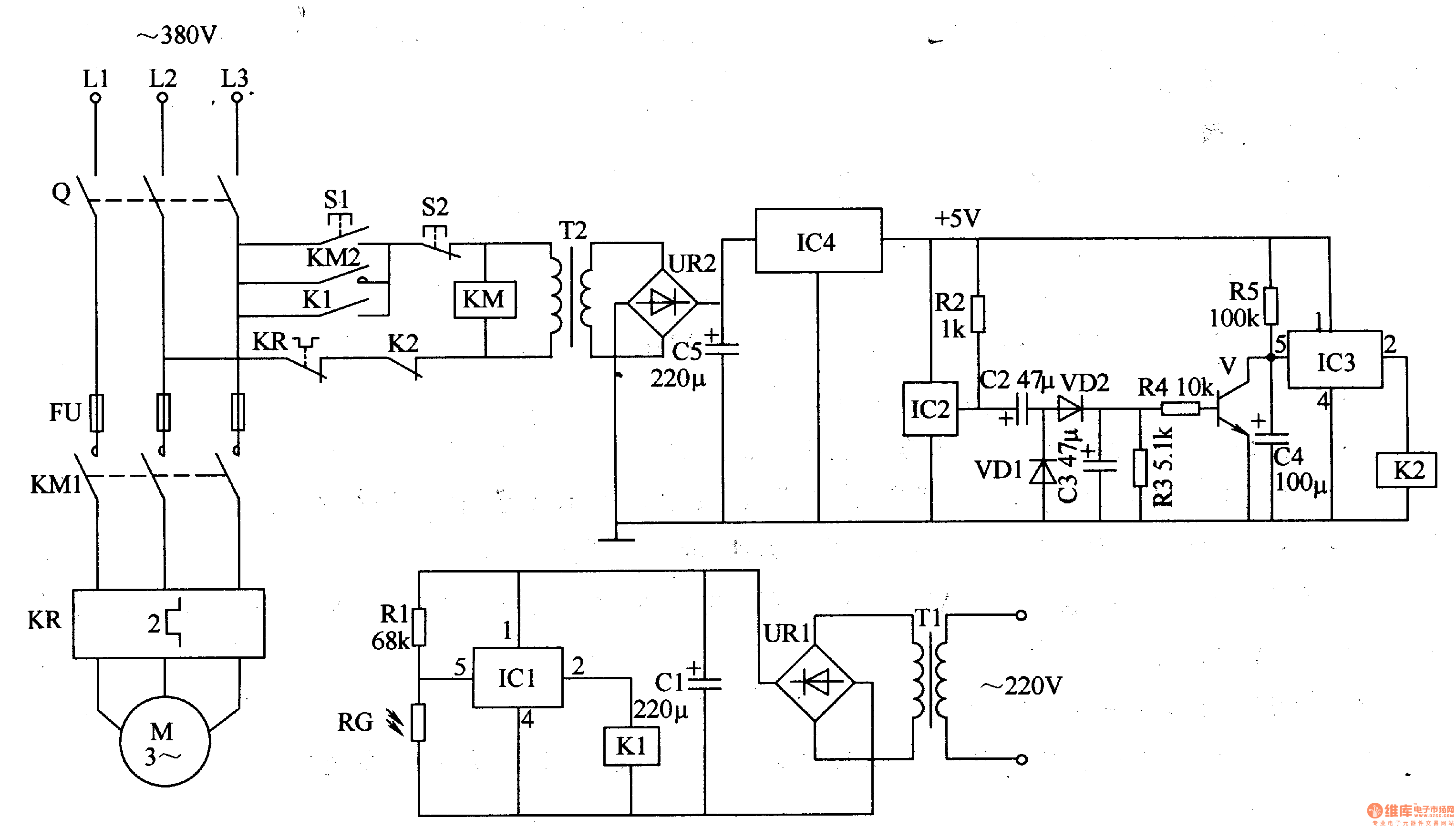
The light control circuit is composed of a photoresistor RG, a resistor R1, an electronic switch integrated circuit ICl, a relay K1, a filter capacitor Cl, a rectifier bridge stack UR1, and a power transformer T1.
The magnetic control circuit is composed of a Hall sensor integrated circuit IC2, a resistor R2-R5, an electronic switch integrated circuit IC3, a capacitor C2-C4, a diode VD1, a VD2, a transistor V and a relay K2.
The +5V power supply circuit is composed of a power transformer T2, a rectifier bridge stack UR2, a filter capacitor C5, and a three-terminal voltage regulator integrated circuit IC4.
The motor main control circuit is composed of a knife switch Q, a start button S1, a stop button S2, a fuse FU, an AC contactor KM, and a thermal relay KR.
During manual control, the knife switch Q is turned on, and the start button S1 is pressed. The KM is energized and combined with the self-locking, and the motor M is energized. Press the stop button S2, KM is powered off and M stops running.
In automatic control, when the driver just puts the foot on the pedal, the light shining on the RG is blocked by the foot, and the RG changes from the low resistance state to the high resistance state, and the voltage drop across the RG increases, so that the inside of the IC1 The electronic switch is turned on, Kl is energized, its normally open contact is connected to the working voltage of the KM coil, KM is energized and combined with self-locking, and M is energized.
At the same time that KM is energized, the secondary winding of T2 generates 6V AC voltage. After this voltage is regulated by UR2, C5 filter and IC4, it provides +5V working power for IC2 and 1C3. When the +5V power supply is just turned on, since the voltage across 4 cannot be abrupt, the 5 pin of IC3 is low, the internal electronic switch is in the off state, and K2 does not pull. As the braker steps on the pedal to start the warping machine, so that the warping machine rotates from slow to normal operation, the permanent magnet rotating synchronously with the warping machine makes the Hall sensor integrated circuit IC2 work, and the pulse voltage generated by IC2 passes through C2. After VDl, VD2 and C3 voltage doubler rectification, a DC voltage is generated across R3 to make V turn on, and C4 discharges to ground through V's conduction internal resistance (the charging voltage of C4 has not reached the turn-on voltage of IC3's 5 pin). When C4 is shorted by V, IC3 is still in the off state and K2 is in the released state.
When the warping machine stops for some reason, the Hall sensor integrated circuit lC2 loses the role of the rotating magnetic field and stops working, so that V is turned off, and C4 is charged again by R5. When the voltage across C4 reaches the turn-on voltage of lC3, the electronic switch inside IC3 is turned on, so that K2 is energized and pulled, and the contact is often disconnected, KM is discharged, and the motor M stops running, thereby saving energy.
When the motor M has an overload or short-circuit fault, the normally closed contact of the thermal relay KR is disconnected, so that KM is released, and M stops, which acts as an overcurrent protection.
Component selection
Rl-R5 selects 1/4W metal film resistor for use.
RG selects the MG45 series of photoresistors.
Cl-C5 selects aluminum electrolytic capacitors with a withstand voltage of 16V.
VD1 and VD2 use 1N4148 type silicon switch diode or 1N4001 type silicon rectifier diode.
Both URl and UR2 use rectifier bridges of lA and 5OV.
V selects S9013 or 3DG6, S8050 type silicon NPN transistor.
Both ICl and IC3 use TWH8778 electronic switch integrated circuit; IC2 selects three-terminal Hall sensor integrated circuit, such as CS6837; IC4 selects LM7805 three-terminal integrated voltage regulator.
Tl selects 3W, the secondary voltage is 6V (220V/6V) power transformer; T2 selects 5-8w, the secondary voltage is 6V (380V/6V) power transformer.
Both Kl and K2 use the Model 4098 6V DC relay.
Sl, S2, KM, KR and FU can be selected using the original warping machine accessories or according to the power of M.


 December 24, 2021